Introduction
Land
and shipboard high-frequency radio
direction finding (HF D/F or Huff
Duff), is now generally recognised
as being with radar and
code-breaking, a primary factor in
the allied victory in the Battle of
the Atlantic against the German and
Italian submarine onslaught against
shipping. Perhaps this is
evenly balanced? However little has
been published about the background of
the work carried out after 1918 to
provide this capability. This Paper
sets out to record some of the various
steps taken at HM Signal School,
Portsmouth to make this possible. It
seems essential that some details must
be given of the transfer of effort
from the improvement of direction
finding on the lower frequency
transmissions then in use, to the
provision of the same service on
signals over 2 MHz. Theoretical
explanations and detailed technical
descriptions have been kept to a
minimum as this type of information is
available in the references.
The
Inter-War Years
This Paper sets out
to record some of the various steps
taken at HM Signal School, Portsmouth
to make this possible, despite the
limited resources and lack of
appreciation of the value of this
operational capability. It does
however seem essential that some
details must be given of the transfer
of effort from the improvement of
direction finding using the radio
transmissions on lower frequencies,
then in use, to the provision of the
same service on signals over 2 MHz. 1.
Use of radio
equipment for communication was well
established before the outbreak of war
in 1914. Part of the development of
this capability had shown that it was
possible to determine with some
accuracy, the relative bearing of a
radio transmitter whose signals on
lower frequencies were being received.
However further investigation by HM
Signal school before the end of
hostilities in 1918 had not provided
any significant results.2 Despite
the
lack priority given to other
work, such as production of suitable
electronic valves for use in radio
transmitters on shorter wavelengths,
work was continued to further develop
equipment for direction finding at
higher frequency transmissions.
It had been
established that the ‘Bellini-Tosi’
system was best suited to use on board
ships. The most important element in
any Radio Direction Finding equipment
is the design of the aerial system
used. Between 1920 and 1930 several
different designs were used. These
ranged from use of two frame coils
fitted within the bridge structure of
large ships which were later replaced
by two large loops. One was of
rectangular shape in the fore and aft
plane and the other of triangular
shape was fitted athwartships. Both
were sited in positions as high as
possible in the foremast structure,
rigged at right angles and bisecting
each other. The total area covered by
these some what extempore arrangements
was about 2,500 Sq. Ft to suit
reception of long wave signals at any
distance. It was recognised that
effect of adjacent land masses on
transmitter sites and also that of
atmospheric conditions at Sun rise and
sunset had to be considered. 1
The various
alternatives using different type of
shaped loops can be identified on
photographs of many contemporary
warships including HM Battleship
WARSPITE
3. In early trials, some
warships these large aerials were at
lower level and fitted between the
funnels or in one funnelled ships
between the funnel and bridge
structure. The beam loop was suspended
from the triatic
stay and connected to stump masts or
booms. This arrangement presented
difficulties in the physical handling
of the portable lengths of wire which
had to be kept rigid using bottle
screws2. Operational
efficiency was affected by the effects
of radiation from the main
transmitting aerial and bearing errors
were also caused by proximity to fixed
structures as well as the movement of
boats or gun mountings. Different
sizes at varying heights in and on
both masts may have been used in some
ships for conduct of trials3.
The main advantage of
fixed rigid loops was to avoid the
problems of rotating such a large
assembly. It also would suit reception
of signals transmitted from positions
over a long distance. Although the
aerial circuit could be tuned this
would require adjustment for each
received signal and introduce large
errors since the exact size of each
loop would not be identical. Use of
tuned aerial circuits was not
continued.
Signals received by
aerials of this design would be of
maximum strength when the loops were
pointing directly towards the position
of the transmitter and be at their
minimum when pointing 90o
away from its
actual direction1.T his had
to established by turning the ships
through a full circle which was
inevitably a long process and could
involve several time-consuming
operations involving significant
man-power. It follows that by use of
two loops there are two positions in
which maximum and minimum signals from
the bearing of the transmitter site
are received. In order to overcome
this ambiguity the two loops are
connected to a Sensefinder1.
This is an angle measuring device,
known as a ‘goniometer’, fed by a
separate input of the same
signal. Accuracy of the
determination of the actual bearing of
the received signal depends on there
being no mutual coupling between the
loops and that the received aerial
current fed from the loops produces a
uniform magnetic field1.
A goniometer
comprises two fixed Field Coils,
connected to the two loop aerials and
a separate rotating Search Coil fed
from a separate Sense aerial. This
Sense signal will not vary and is 90o
out of phase with
that from the loops. As result of
this, the combined signal sent to the
main receiving circuits is modified by
movement of the rotating component
There are two
positions when the received signal is
at maximum during one complete
rotation. When turned clockwise the
true bearing as indicated on the
Bearing Indicator Dial is being
received. However due to the
combination of the Sense aerial input
with that from the two loops, the
reciprocal bearing is identified when
the signal strength increases (See
Figure 21 in Reference 1).
Transmissions on
frequencies about 600 KHz were a more
complex matter because of the effect
due to movement of layers in the
ionosphere. Use of a super-heterodyne
receiver was more efficient at higher
frequencies. Shore trials at a special
establishment exclusively for aerial
design were carried out first. During
trials at sea using one of the loop
aerials to instead of a separate Sense
Aerial proved unsatisfactory compared
with results obtained when a
completely separate wire aerial was
used.1. Amongst the factors
considered during these early trials
was the effect of coincident wireless
transmissions on trials ships when
direction finding was being carried
out and these were forbidden. It was
also found that during reception of
signals on higher frequencies,
significant bearing errors were caused
by ship’s rigging, ship structure and
the movement of gun mountings or
boats. In addition it was discovered
that the physical length of the ship
also had an influence on the accuracy
of bearing errors on frequencies whose
wavelength was related to the received
signals. It was therefore evident that
improvement had to be made to the
aerial design in order to reduce
bearing errors although this could not
be eliminated on some frequencies2
After 1930 a single
rotating loop aerial of circular
design were installed in some warships3
(HMS
BARHAM)
instead of these large loops. It was
then realised that smaller ‘diamond
shaped’ rotating doubled loops would
be more successful on higher
frequencies than the some what
extempore fittings previously used on
large ships. Clearly they would also
be much more suitable for fitting on
smaller vessel, especially destroyers.
This proved to be most significant
step and the fixed Frame coil design
used had two rotatable smaller loops
and became a standard fit in TRIBAL
Class destroyers on build before
September 19393. The final
design used one of two different
designs of aerial units, identified as
Frame Coils S16 and S17. These were of
different sizes, that of S16 being 3ft
square and S17 of 4ft 6” square. The
size of aerial used depended on the
structure of structure of particular
ships mast. The aerial unit was
mounted on a pole mast fitted at the
top of foremast of the ship. Both
Frame Coil and Pole-mast could be
struck using a separate beam to lower
or raise the complete assembly when
necessary to allow passage under a
bridge or for replacement.
Much more attention
was paid to further development of H/F
DF after 1931 and trials were carried
out in HM Cruiser CONCORD using a
rotating aerial fitted on the roof of
the spotting top sited at the top of
the foremast. Results using high
frequencies revealed errors in bearing
varied on various frequencies were due
to ship’s rigging, and the length of
the ship. In addition, efficient earth
connections had to be used for the
aerial cabling. It was essential to
site the receiving equipment as near
as possible to the aerial loops and
the receiving equipment was fitted on
the mast structure for the
installation in HMS CONCORD2.
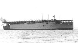
Trials were carried
out on an aircraft carrier, probably
HMS ARGUS
in 1938 for further investigation. As
this vessel had no masts or rigging it
was possible to establish the effects
of factors other than re-radiation
from these. By this time an improved
design of goniometer to suit use on
higher frequencies had been developed.
Installation of D/F equipment had been
completed on many other warships
before the outbreak of war. HM
Battlecruiser
RENOWN
had fixed loops; HM Battleship
BARHAM retained fixed loops of the
mainmast. as
well as the fixed loops on the
mainmast. HM Cruiser
AURORA
also had two rigid loops whilst HM
Cruiser
MANCHESTER
was fitted with a rotating Frame
Coil similar to the TRIBAL Class
destroyers. Soon after the outbreak
of war HM Cruisers EURYALUS
and
BONAVENTURE
had
rotating frame coil aerials3.
In all these ships, existing
receiving units,
modified to accept separate
inputs from two loops, were used with
Sense Aerial Tuners, Heterodyne
Receivers and Amplifiers. The
receiving circuits of the
these items did not
incorporate provision for elimination
of ambiguous bearing indication when
used for higher frequencies because of
the errors caused by structure and
other factors. However all low
frequency receiver units used a
goniometer.
D/F in Submarines
The trials after 1930
included work on submarines which
particularly relied on reception of
long wave transmissions. Initially,
frame aerials sited within the conning
tower structure were used and it was
found that these good results on low
frequencies. Subsequent trials were
carried out using a two fixed loops
attached to the periscope but this was
replaced by fixed loops fitted on the
hull of the boat aft of the conning
tower. The main aerial used for the
main transmitter was used for sense
finding3.
Developments after
1939
Before the outbreak
of war in 1939 it had been decided
that D/F aerials used for frequencies
above 2MHz must be sited at the
highest point possible to minimise
errors due to the surroundings. A new
design of Bellini-Tosi
aerial using two rigid loops was
required with the Sense aerial
positioned at exact centre of
its framework. A
counterpoise ‘earth’ was incorporated
in the design of the aerial unit4.
By introducing an adjustable
capacitance it was possible to reduce
amount of current induced in the Sense
Aerial by the support mast thus
reducing the amount of unnecessary
content provided to the receiver for
sense finding.
This was a most vital
discovery and enabled an operationally
effective system identified as FH1 to
be produced in HM Signal School.2
During
March 1941, the first RN HF D/F Outfit
was installed in HM Destroyer HESPERUS
as Outfit FH1 after the completion of
trials on the new Frame Coil S25 in
cruisers4. Further trials
had to be arranged in convoy escorts
with priority for fitting given to
those deployed for ant-submarine
defence. However the selection of
position introduced conflict between
ship designers and users which was
hard to resolve satisfactorily. In
both cases, choice
of the site to be used had to take
due account of the arcs of fire of
weapons and the positions of other
wireless aerials. Mandatory
requirements associated with topside
stability and electronic
interferences, in the early stages
of development, made it
impossible to fit both radar and
Huff Duff on the same ship2.
Most
escorts had the unit fitted on the
mainmast aft in order to enable a
surface warning radar set to
be fitted on the foremast. In post war
years the aerial was generally fitted
on a pole mast forward, above the
radar aerial. An improved version of
FH1 was introduced during July 1941,
identified as Outfit FH3 and installed
in HM Destroyers GURKHA and LANCE2.
These equipments all used the
‘aural-null’ method to establish the
true bearing of signals but work was
in hand to introduce a method of
visual presentation instead. This
would enable less skilled operators to
rapidly establish and interpret the
true bearing of signals received.
Twenty five escorts and rescue ships
had been fitted with FH3 by January
1942.
Distance from the
transmitter was impossible to
determine accurately, but operators
soon learned to distinguish HF ground
waves from sky waves. Since ground
waves could only be detected 12 to 14
miles from the transmitter, FH3
operators knew when an intercepted
signal represented a dangerously close
U-boat. The FH3 incorporated the B21B
receiver which had a
frequency coverage from 1 to
20 Mc. By the end of January
1942 25 escorts and some
rescue ships were fitted with an
improved version.
The
improved version, FH4, used a
cathode ray tube display and was
fitted in HM Cutter CULVER, the ex
US Navy Coastguard Cutter USS
MENDOSA during October 1941
Production of the FH4 Outfit was
developed and produced by Plessey
Company which included a ‘twin
channel’ receiver developed by the
company.
In
this improved equipment each of the
loops were connected to separate
identical amplifying receiver units
which could be balanced for phase
shift and gain in order to provide
outputs to the deflecting plates of
the cathode ray tube.. This ensured
that the resulting display would
show when any phase differences
existed in the signals being
received from the two loops. If ‘in
phase’ a single line will be
displayed, but if the phase from one
loop differs an elliptical trace
will be shown., A Sense aerial is
incorporated in the design of the
Frame Aerial, S25B as shown in the
diagram4 and ensures
that the bearing display is ‘true’5.
The visual display of signals made
it easier to distinguish ground wave
signals since these were much
stronger and the length of the
displayed single line would be
greater and indicate the range of
the position from which the
transmission was being made. This
was a vital factor in successful
defence against submarine attack as
U-Boat transmission were of very
short duration and visual display
provided in FH4 was easier for an
experienced operator to assess.
Although Sky wave signals reflected
from ionospheric layers were of
lower strength and made bearing and
range determination unreliable.
Ground wave signals at ranges up to
12 miles made both factors much
easier to determine since the
signals were much stronger. A Test
facility is included in FH4 design
to balance the operation of the two
receiver systems.
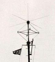
right
- HD/DF aerial believed on destroyer
escort USS Francis M Robinson DE220
(US Naval Historical Centre)
The
first of 30 production models was
available in March 1942 and fitted
on board HM Destroyer LEAMINGTON (Ex
USS TWIGGS.) and later that year on
a few other convoy escorts and
rescue ships. This outfit because a
standard fit in all RN vessels
requiring a direction finding
capability and was in use for the
rest of the 21st century.2.
During service this equipment also
proved invaluable for other use than
convoy defence. It was used for
tactical purposes to establish
positions of ships in a Task Group
which were required to change
position during a current operation.
For example, during the Home
Fleet operation in December
1943 to intercept the German battle
cruiser SCHARNHORST HF D/F was very
effectively
used to engage the enemy ship and
also cover the passage of vital
supply convoy. It also provided a
more reliable method of establishing
ship’s position from Shore Beacons
when in poor weather.
Shore
stations
The
development of suitable equipment
for locating the position of U-Boats
which proved to be essential
requirement in meeting
the threat to convoys. The
bearings of transmissions by U-Boats
could be determined by two or more
shore stations and passed to the
convoy escort commander. This
information enabled course of
convoys to be changed to avoid the
threat and for escorts fitted with
HF D/F to search for transmissions
and carry out search and destroy
operations by following the bearings
indicated by transmissions. Soon
after the more important work by HM
Signal School on ship equipment
allowed it was decided that the most
suitable aerial design
for shore station
equipment would be an Adcock system.
Vertical dipoles were used for
detection of signals on both low and
high frequency transmissions
Initially wire aerials suspended
from high masts were used for
earlier outfits but later
arrangements used smaller rotating
aerials sometimes in mobile vans,
After introduction of the S25 Frame
Coil for FH4 this was used at shore
stations and in mobile units for
high frequency requirements.
HF
D/F
Research and Development in allied
countries
In
France, pre-war R&D on Huff Duff
was carried out at the Laboratoire
Telephonique
in Paris, a subsidiary of
International Telephone and
Telegraph (ITT).This work paralleled
that of the British,
with whom the French shared
electronic secrets until the Germans
overran France in May 1940. Some of
the engineers were able to get to
the USA via Spain early in 1941.
They were allowed to work on naval
HF D/F equipment, but were not fully
trusted.
The
US.
Navy, experimenting with its own
shipboard Huff Duff models as well
as the British FH3, was slow to
embrace the new ideas. Like the
Royal Navy, US warship captains
preferred radar to ‘Huff Duff’.
However by 1942 after comparative
trials between use of FH3 and an
a US designed outfit, a US
design, Outfit DAQ was chosen. Over
four thousand outfits were
produced and fitted in all new
destroyers and escorts.
Once
the development of satisfactory
equipment for use at sea on high
frequency transmissions had been
completed it was possible to begin
work on development of suitable
outfits for use an
Very High Frequencies (VHF). There
had been a most significant increase
in use of VHF equipment in aircraft
and in escorts for communication
during convoy defence and other
operations. In aircraft carriers,
immediate knowledge of positions of
ships and aircraft was essential and
made possible by the availability
these new facilities. By 1945
direction finding outfits for use on
VHF transmissions was available on
some aircraft carriers deployed in
the Far East and proved invaluable
for navigation and the safety of
aircraft during Fleet operations as
well as in inclement weather.
Several Dipole aerials arranged in a
circular formation are used for
these D/F outfits.
Post
War Development
In
the immediate post war years
direction finding on Ultra High
Frequencies (UHF) was successful.
This band is now in general use for
all inter-ship communications as
well as for all aircraft radio
communication requirements. As a
natural progression similar progress
has been made on the provision of
equipment suitable for use on radar
transmissions and is now widely used
for many defence requirements. Since
the much shorter wavelengths are
used four individual ‘Horn Type’
aerial units are used for each
different radio frequency
band. These are installed in the
Fore and Aft and Athwartships
planes.
Conclusions
No better
confirmation of the satisfactory
development of HF D/F equipment in
Great Britain before and during WW2 is
the German admission after September
1945 that their
own work on this particular
research had been inadequate. It was
admitted that during WW2 they had
experienced great difficulty in
locating the position of U-Boats. Pre
war work in UK before September 1939
had been severely restricted by the
resources provided by the Admiralty
despite the recognition by a few
senior officers that any work on this
subject was an obvious essential to
the conduct of war at sea..
References:
1.
ADMIRALTY HANDBOOK OF
WIRELESS TELEGRAPHY (HMSO 1938)
2.
AS WE WERE Unpublished
account of the work of HM Signal
School 1896-1946
(Later
Admiralty Signal and Radar
Establishment.)
3.
Photographs showing Aerial Units
4. Drawing of FH4 Frame Coil (S25).
Other Sources:
HITLER’S U-BOAT WAR
by C Blair, Volume 1, Appendix 8
(1999)
SECRET WEAPON by KM
Adams (1996)
RADAR AT SEA by D Howse
(1993)
Acknowledgement:
The
Curator, Radar and Communications
Museum, HMS COLLINGWOOD, Fareham,
Hants.